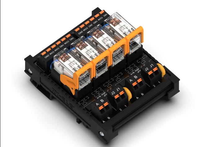
Installing a relay socket on a control board requires more than checking whether the component fits the available space. Engineers need to review electrical ratings, pin arrangements, PCB dimensions, mounting requirements, and operating conditions before installation. These checks help reduce connection problems and support dependable equipment operation.
A PCB relay socket provides the connection between a relay and its printed circuit board, so compatibility deserves careful attention before assembly. RY-ELE develops relay and control components for applications that require reliable electrical connections and practical maintenance options.
Start With the Relay Specifications
The relay should always serve as the starting point for socket selection. Different relay models may have different terminal layouts, dimensions, coil requirements, and contact arrangements.
Engineers should obtain the relay datasheet and verify its specifications before ordering or installing a socket. This simple step can prevent compatibility issues later in the assembly process.
Check the Pin Configuration
Pin configuration ranks among the most important installation checks. The socket terminals must correspond with the relay’s actual pin arrangement.
Verify:
- Number of relay pins
- Pin spacing
- Terminal functions
- Coil connections
- Contact arrangement
- Pin orientation
Two relays may have a similar appearance while using different terminal assignments. Never rely on physical appearance alone when confirming compatibility.
Verify Electrical Ratings
The socket should support the electrical requirements of the relay and the circuit. Engineers need to consider voltage, current, switching conditions, and the intended application.
Operating components beyond their specified limits may cause excessive heating, contact degradation, or premature failure. Reviewing the ratings before installation helps ensure that the selected components suit the control system.
Examine the PCB Footprint
Before mounting the socket, compare its dimensions with the PCB layout. The footprint should correspond accurately with the board’s holes, pads, or other mounting features.
Engineers should also check the space surrounding the socket. Nearby components may interfere with relay insertion, removal, wiring, or inspection.
A suitable footprint supports cleaner assembly and reduces the risk of mechanical conflicts.
Inspect the Socket Before Installation
A visual inspection can identify problems before the component reaches the production stage. Check the socket housing, terminals, mounting points, and other visible features.
Look for signs of physical damage, bent terminals, cracks, contamination, or manufacturing defects. Damaged components should not enter the assembly process.
This inspection takes little time but can prevent avoidable installation issues.
Review PCB Condition
The PCB itself also needs inspection. Solder pads, drilled holes, traces, and surrounding areas should meet the requirements of the socket.
Any damaged pad or poorly formed hole may affect mechanical stability or electrical continuity. Engineers should address PCB defects before installing the socket rather than attempting to compensate during assembly.
Confirm Mounting Orientation
Correct orientation matters when the socket has a defined terminal arrangement. An incorrectly positioned socket may create connection errors even when the component physically fits the board.
Clear markings, PCB references, and assembly documentation can help technicians install the component consistently.
Design teams should make orientation information easy to identify during production and future maintenance.
Consider Soldering Requirements
The installation process should match the socket’s terminal and mounting design. Solder joints need to provide reliable electrical and mechanical connections without damaging the socket or PCB.
Excessive heat, insufficient solder, or poor soldering technique may compromise the connection. Production teams should follow the component manufacturer’s recommended assembly conditions.
Automated assembly processes also require attention to placement accuracy and soldering profiles.
Think About Temperature
Engineers should evaluate the expected temperature around the relay socket. Heat may come from the relay itself, nearby power components, or the surrounding equipment.
The selected socket materials should suit the application’s operating temperature range. Proper thermal planning helps protect the socket, relay, PCB, and nearby components.
Compact control boards deserve particular attention because components often sit close together.
Evaluate Mechanical Stress
Industrial equipment may experience vibration, shock, or repeated movement. These forces can affect sockets, solder joints, and PCB connections over time.
Engineers should ensure that the socket provides suitable mechanical support for the application. The relay should also fit securely without excessive movement.
Applications with significant vibration may require additional attention to mounting and equipment enclosure design.
Plan for Maintenance
A socket can make relay replacement easier, but engineers should consider accessibility during the original PCB design.
Technicians need enough room to remove the relay without damaging neighboring components. Equipment designers should also consider how frequently the relay may require replacement.
A small amount of additional space around the socket can make future servicing much easier.
Check Environmental Conditions
The installation environment can influence component selection. Industrial control systems may encounter humidity, dust, vibration, temperature changes, or other operating stresses.
Engineers should compare these conditions with the socket’s specifications. Enclosures, ventilation, and appropriate PCB protection can also help reduce environmental exposure.
Understanding the actual operating environment allows designers to make a more suitable component choice.
Follow the Manufacturer’s Specifications
Manufacturer documentation provides important information about compatibility, installation, ratings, dimensions, and operating conditions.
Engineers should review the relevant technical information before approving a socket for production. RY-ELE documentation can help designers evaluate relay-related components according to their specific application requirements.
Following documented specifications also gives assembly and maintenance teams a consistent reference.
Final Installation Checklist
Before installing the socket, engineers can use a simple checklist:
- Confirm relay and socket compatibility.
- Verify the pin configuration.
- Check voltage and current ratings.
- Compare the socket footprint with the PCB.
- Inspect the socket for physical damage.
- Examine PCB pads and mounting points.
- Confirm orientation.
- Review soldering requirements.
- Evaluate temperature and environmental conditions.
- Check accessibility for future maintenance.
Completing these checks before assembly can reduce errors and improve production consistency.
How RY-ELE Supports Relay Applications
RY-ELE provides relay and control components for electrical and industrial applications. Engineers can evaluate product specifications alongside their relay and PCB requirements to select components that fit their intended system.
A careful installation process helps ensure that the relay, socket, and PCB work together correctly. Proper preparation also supports easier maintenance and more consistent equipment performance.
Conclusion
Engineers should check compatibility, pin configuration, electrical ratings, PCB dimensions, mounting orientation, soldering requirements, environmental conditions, and maintenance access before installing a relay socket.
These details may seem straightforward, but each one can influence the reliability of the finished control system. Careful preparation reduces installation errors and helps create stable connections for industrial equipment.
With suitable component selection and proper assembly practices, RY-ELE relay solutions can support dependable electrical control and practical maintenance requirements.